The determination of the theoretical intersections between digital 3D geological surfaces and topography could be of potential help for studying the field attitudes of natural geological surfaces, as mapped from outcrops or from aerial and satellite images. Since geological structures have complex geometries, the analysis of the relationships between 3D surfaces and topography requires tools that can process 3D geological surfaces.
geoSurfDEM aims at determining:
a) the theoretical intersections between a 3D surface and a topography
b) the local 3D attitude of that surface at each intersection point
How does it work?
Below you see the screenshot of an application run in a Linux shell. When compiled for Windows, the procedure is identical. The total run time can be quite long, many minutes or more.
What is to note?
After the application header display, the user is asked for the name of a text file. In this example, "input_files.txt" is provided, the name of a file located in the same directory as the running application. This file provides the paths of three files:
1) DEM, in ESRI ASCII grid format
2) geological surface, in (old) VTK text format
3) output csv file storing for each row: x-y-z-dip direction-dip angle
An example of input text file is the following:
./publ_data/dem_malpi_aster_wgs84utm33.asc
./publ_data/geological_plane.vtk
./publ_data/intersections.csv
Examples of input data files (i.e., DEM ASCII grid, VTK geosurface file, CSV intersection result) are present in the publ_data subdirectory.
Afterwards, the application outputs a few informative messages about the number of found features and at the last prints out the number of found intersecting points, hopefully greater than zero. The results are stored in the text file referenced by the third path in the input text file.
Example of use
To present the application and check the validity of its results, we use a theoretical test case, i.e. a geological plane with a desired attitude 135°/35°, and with a spatial extent fitting that of the test DEM, covering the Mt. Alpi zone (Basilicata, Southern Italy), derived from global ASTER data.
You can export a DEM in ESRI ASCII grid format with Saga GIS (in addition to ArcGIS).
Creation of test geological plane
The geological plane is created and saved as a VTK text file with simSurf. With this Python 2.7 tool, it is possible to simulate geological surfaces by using analytical formulas.
simSurf is subdivide in two modules:
a) geosurface_simulation.py: creates, geolocates and saves/exports an analytical surface
b) geosurface_deformation.py: reads an analytical surface created by the previous module, deforms it and saves/exports.
Horizontal plane creation
So we start creating a horizontal plane with the Geosurface simulation tool, Analytical formula part, see figure below.
The zero in the formula section is for the horizontal plane creation. You calculate the matrix and you can see the plane in three dimensions.
Then to the geographical parameters, that have to fit the DEM extent without creating an excessively large geological plane.
We create the simulated geosurface, optionally view it in three dimensions and then have to export it in the Geo Analytical Surface (GAS) format, i.e. a jason format.
Plane rotation
We then pass to the Geosurface deformation tool, import the previously exported jason file and then apply a rotation to the plane around a N-S horizontal axis, by 35°.
Apply and then rotate by 45° around a vertical axis (plunge equal to 90°).
In this way we obtain a plane dipping 35° towards N135°.
Plane displacement to DEM extent
Now we locate the rotated plane to a geographical position that broadly fits with the DEM. I choose to use my qgSurf plugin for QGIS for quickly locating a point at the center of the used DEM, while knowing also the z value.
You see to the right the coordinates (x-y-z) of the point at the DEM center, showed within QGIS.
I copied and pasted these values in the simSurf displacement tab, so that the plane is displaced by the given delta-x, delta-y and delta-z amounts.
Done, after applying.
Save the geosurface as a VTK file and then you can see it in Paraview and use in the geoSurfDEM application. Note that the VTK file stores the plane as triangle mesh, without explicit attitude (i.e., dip direction and angle) information. So the local results calculated by the geoSurfDEM application are derived by the local geosurface triangle attitude stored in the VTK file. Using a simple plane obviously we expect the same results for all intersection points.
Input data preview
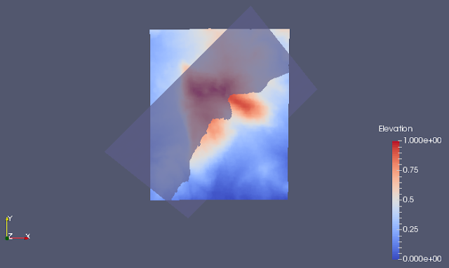
We see how are the DEM and the VTK plane data in Paraview.
You can import the DEM when in x-y-z format (could create with Saga), then applying a
Table to Point filter, while the VTK format is directly read from Paraview. Here a nadiral view.
Y axis represents the North.
And a lateral one, as seen from the South.
geoSurfDEM result
At the end, what are the results of the geoSurfDEM application?
We see them displayed in Paraview, by importing the resulting csv file and superposing on the DEM points and the plane surface. The results are symbolized by blue dots. You see them following the visual intersection between the plane with dip direction 135° and dip angle 35° and the DEM.
Always in Paraview we see, for a few records, that the corresponding point attitudes calculated by geoSurfDEM are as expected: 135°/35° for each point, since in this test case we were dealing with a geological plane.
----------
The code repository of geoSurfDEM is at https://gitlab.com/mauroalberti/geoSurfDEM
Executables for Linux are also availables for Linux (64 bit) at the code repository.
EDITS:
2023-01-01: fixed broken llinks to images


No comments:
Post a Comment